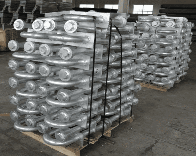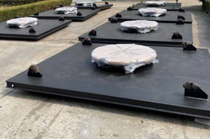
Cell Fender Systems
- High Energy Absorption
- Low Reaction Force
- Compact Structural Design
- Optional Steel Front Panel and Facing Pads
SME Marine manufactures cell fender systems for ports, terminals, shipyards and marine infrastructure projects. These systems absorb berthing energy while helping control reaction force. Depending on vessel size and berth conditions, steel front panels and facing pads can also be supplied to meet specific project requirements.
Request a QuoteCell Fender System Configuration
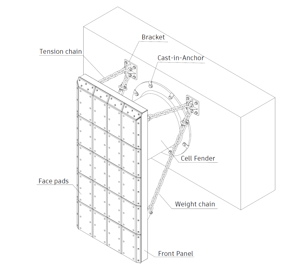
A typical cell fender system combines a rubber fender body with a steel front panel, facing pad and chain accessories. However, the final arrangement depends on berthing conditions, vessel characteristics and project specifications.
Cell Fender Product Details
Different rubber body sizes and front panel arrangements are available to accommodate varying berthing conditions. The following components illustrate the main elements of a typical cell fender system.
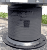
Rubber Fender Body
The cylindrical rubber body absorbs energy as a vessel approaches the berth. Its performance depends on the selected model, deflection and specified operating conditions.
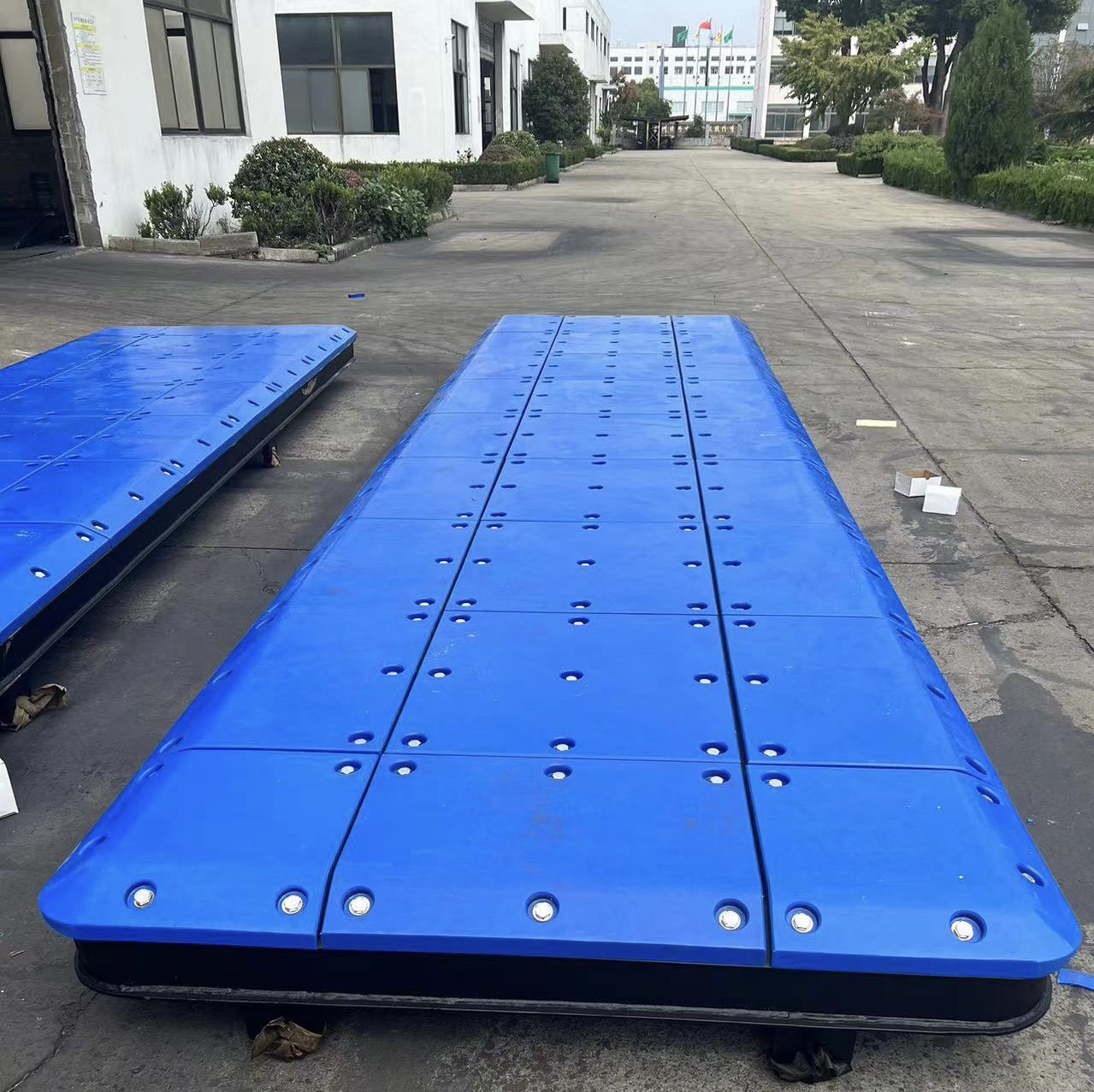
Steel Front Panel
A steel front panel distributes contact loads across the fender face. Suitable facing pads can be fitted to provide the required contact surface for the vessel.
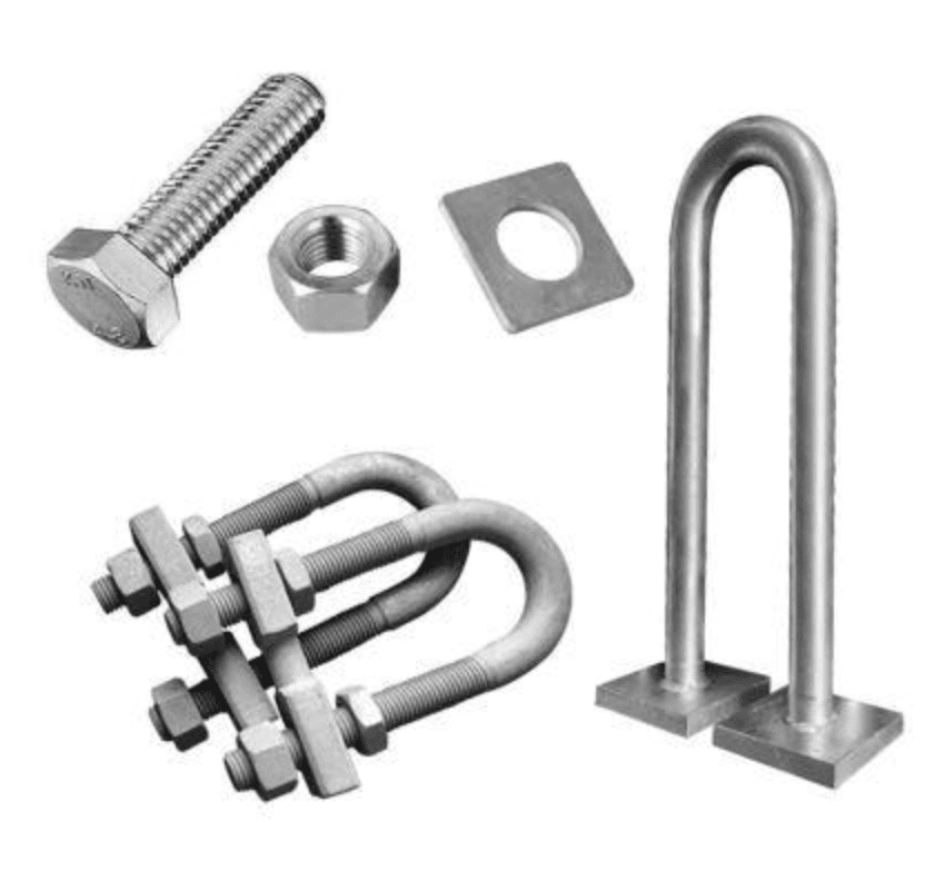
Fender Accessories
Chains, anchors and other accessories support the installation and positioning of the fender system. Their arrangement follows the approved installation design and project requirements.
Technical Specifications
SME Marine cell fender systems cover standard models from SC 400 to SC 3000. Selection depends on the required energy absorption, allowable reaction force, deflection and berthing conditions. For accurate performance values, refer to the technical datasheet for the selected model.
- SC 400
- SC 500
- SC 630
- SC 800
- SC 1000
- SC 1150
- SC 1250
- SC 1450
- SC 1600
- SC 1700
- SC 2000
- SC 2250
- SC 2500
- SC 3000
Performance & Model Selection
Energy absorption and reaction force differ by model and deflection. Therefore, the final selection should consider the required berthing energy, allowable reaction force, installation arrangement and approved project specifications. Detailed performance data can be provided for the chosen model.
Materials & Design Standards
Rubber composition, design references, steel panel protection, service life and warranty all contribute to the specification of a cell fender system. The final requirements should be checked against the needs of each marine project.
Rubber Material
- Natural rubber content: More than 55%
- Recycled rubber core: Not used
- Rubber compound selection is based on the required fender performance and applicable project specifications.
Design Standards
- PIANC WG211 (2024)
- EAU 2004
- BS 6349 Part 4
Applicable design references should be confirmed against the project requirements and specified edition.
Steel Front Panel Coating
Standard Coating
- Surface preparation: SA 2.5
- Reference: ISO 12944-5:2018
- Dry film thickness (DFT): 325 μm
- Colour: Black
Enhanced Coating Specification
- Corrosion category: C5
- Durability: VH
- Exposure: CX / Im4
- Colour: RAL 9017
- NDFT: 450 μm
Final coating requirements are subject to the project specification.
Design Life & Warranty
- Design life: 20 years
- Warranty: 12 months
Actual service life depends on operating conditions, installation quality, maintenance and environmental exposure. Warranty terms are subject to the supply agreement.
Applications of Cell Fender Systems
Cell fenders are used across a range of marine facilities. Depending on vessel characteristics and berth conditions, each system can be configured to meet the project's protection and installation requirements.
Commercial Ports
For commercial port berths, cell fenders provide protection during vessel berthing across a range of vessel types.
Container Terminals
At container terminals, model selection considers vessel size, berthing energy and allowable reaction force.
Bulk Terminals
Bulk cargo berths may require specific energy absorption and reaction force performance. The fender arrangement is selected according to the terminal's operating conditions.
Shipyards
In shipbuilding and repair facilities, cell fenders help protect berthing structures during vessel docking and maintenance operations.
Naval Facilities
For naval berths, the system configuration is determined by berth layout, vessel characteristics and operational requirements.
Offshore Facilities
Cell fender systems may also suit selected offshore and marine structures, subject to project-specific engineering assessment.
Need Cell Fender Systems for Your Project?
SME Marine supplies cell fender systems for port construction and marine infrastructure projects. To help determine a suitable configuration, provide your required model, berthing energy, allowable reaction force, front panel arrangement and installation details. Our team can then review the project requirements and discuss an appropriate solution.
Request a QuoteProject Gallery
Where Our Fender Systems Perform
Widely used in commercial ports, container terminals, bulk terminals, naval bases and offshore facilities.
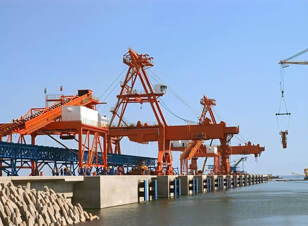
26 pcs of SC 1450H cell fender systems applied to Datang International Power Plant Coal Mine Terminal.
36 pcs of double cell fender systems used in Kribi Deepwater Terminal in Cameroon.
Cone Fender vs Cell Fender: Which One Is Better for Your Dock?
Choosing the right marine fender system is essential for protecting vessels and port structures during berthing. Among the most widely used fixed fender systems, cone fenders and cell fenders provide reliable energy absorption and long-term performance.
However, these two systems differ in structural design, deflection characteristics, installation requirements, and cost. Therefore, understanding their differences helps port operators, marine engineers, and project owners select a suitable solution for their berthing conditions.
In this guide, we compare cone fenders vs cell fenders, including their advantages, applications, and key selection criteria. As a result, readers can better understand which system may suit their project.
1. What Are Cell Fenders?
Cell Fender Design and Structure
Cell fenders are cylindrical, hollow rubber units designed to absorb berthing energy through controlled deformation. Because of their robust structure, they suit a wide range of port and harbour applications.
A typical cell fender system includes a rubber fender body, a frontal steel panel, and UHMW-PE facing pads. Together, these components help distribute contact pressure across the vessel's hull.
Key Advantages of Cell Fenders
- Proven Design: Cell fenders have a long track record in port and harbour projects worldwide.
- Reliable Energy Absorption: They provide dependable energy absorption and reaction force characteristics when properly selected.
- Modular Configuration: In addition, frontal panels and facing pads can be configured to suit project requirements.
- Practical Maintenance: Individual components can be inspected and replaced when necessary. Consequently, damaged components may be serviced without replacing the entire system.
Typical Applications of Cell Fenders
Cell fenders are commonly used at bulk terminals, container berths, general cargo docks, and Ro-Ro terminals. For example, they can provide a practical solution for established berth designs where the required performance can be achieved economically.
Explore our Cell Fender Systems for product details and available configurations.
2. What Are Cone Fenders?
Cone Fender Design and Working Principle
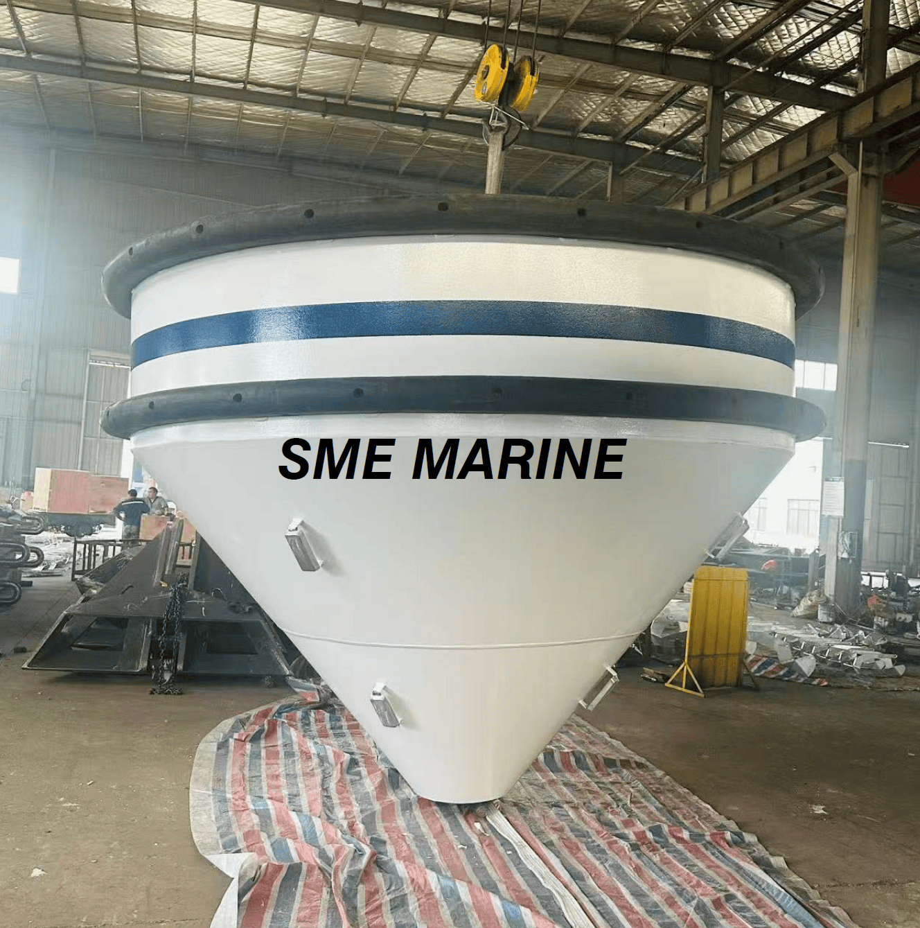
Cone fenders feature a tapered, conical rubber body that allows substantial deformation under compression. Compared with traditional cell fenders, their geometry can provide higher energy absorption relative to size in suitable designs.
As a result, cone fenders are often considered for projects requiring high energy absorption and efficient use of installation space. Furthermore, their design can offer advantages under angled berthing conditions when the complete system is properly engineered.
Key Advantages of Cone Fenders
- High Energy Absorption: Their geometry can deliver high energy absorption within a compact installation.
- Efficient Space Utilization: Consequently, cone fenders may help reduce the footprint required for a given performance target.
- Angular Performance: Properly designed systems can accommodate angled berthing conditions.
- Flexible System Design: In addition, engineers can select suitable frontal panels, facing pads, and mounting arrangements according to project requirements.
Typical Applications of Cone Fenders
Cone fenders are used at container terminals, oil and gas terminals, offshore facilities, and berths serving large vessels. In particular, they may be suitable when a project requires high energy absorption within limited installation space.
Explore our Cone Fender Systems for more information about designs and configurations.
3. Cone Fender vs Cell Fender: Performance Comparison
Key Differences Between Cone and Cell Fenders
Both systems can provide reliable berthing protection. However, their suitability depends on energy absorption requirements, allowable reaction force, installation space, and project budget.
| Comparison Factor | Cell Fender | Cone Fender |
|---|---|---|
| Energy Absorption | High, depending on size and grade | Often higher relative to size |
| Reaction Force | Designed to meet project limits | Designed to meet project limits |
| Angular Berthing | Depends on system configuration | May offer advantages due to its geometry |
| Installation Space | Depends on required performance and unit size | Can offer a compact solution in suitable designs |
| Maintenance | Practical when components are accessible | Depends on system and component design |
| Initial Cost | May be economical for standard applications | Depends on size, facing system, and specifications |
| Typical Use | Standard and established berth designs | Projects with demanding energy or space requirements |
How to Evaluate Fender Performance
In practice, fender performance depends on unit size, rubber compound, rated deflection, berthing velocity, temperature, and other design conditions. Therefore, engineers should compare technical performance data rather than selecting a fender based on type alone.
For a fair comparison, both systems should be assessed under the same design conditions. In addition, reaction force and hull pressure must remain within the limits specified for the project.
4. How to Choose the Right Fender for Your Dock
Selecting between cone fenders and cell fenders requires a review of vessel characteristics, berth layout, and operating conditions. The following factors can help guide the selection process.
Vessel Size and Berthing Energy
Larger vessels may generate greater berthing energy. However, vessel size alone does not determine the required fender capacity. Engineers must also consider displacement, approach velocity, berthing angle, eccentricity, and the applicable project design criteria.
Available Installation Space
Where space is limited, cone fenders may offer an advantage because of their energy absorption characteristics. Nevertheless, the complete system, including frontal panels and mounting hardware, must fit the available space.
Reaction Force and Hull Pressure
The fender system must absorb the design berthing energy while keeping reaction force and hull pressure within acceptable limits. Both cone and cell fenders can be engineered to meet project-specific requirements. Therefore, the final choice should be based on verified performance data.
Maintenance and Replacement
Maintenance requirements depend on the overall system design and operating environment. For example, engineers should consider access to rubber units, frontal panels, chains, anchors, and other components when planning inspections and future replacement.
Budget and Service Life
Initial price is only one part of the decision. In addition, project owners should compare transportation, installation, inspection, maintenance, and potential replacement costs over the intended service life.
Final Selection Considerations
Ultimately, the best solution is the system that meets the project's engineering requirements while providing an appropriate balance between initial cost and long-term performance. For this reason, engineers should evaluate the complete fender system rather than focusing on the rubber unit alone.
5. Cone Fender vs Cell Fender: Cost and Service Life
Comparing Initial Fender Costs
Cone fenders may provide a more compact solution for applications requiring high energy absorption. On the other hand, cell fenders can be cost-effective when their performance already meets project requirements.
However, the initial purchase price alone does not determine the overall value. The total cost of either system depends on rubber specifications, fender dimensions, frontal steelwork, UHMW-PE pads, anchorage, transportation, installation, and maintenance.
Factors Affecting Fender Service Life
Service life depends on rubber quality, operating conditions, environmental exposure, installation quality, and maintenance practices. Therefore, it is not accurate to assume that one fender type always lasts longer than the other.
Evaluating Long-Term Ownership Costs
For a fair comparison, review the specified service life, inspection requirements, and expected maintenance costs. In addition, consider the accessibility of replacement parts and the potential disruption caused by maintenance work.
As a result, comparing lifecycle costs provides a more useful basis for selection than comparing initial purchase prices alone.
6. Conclusion: Which Fender Is Better?
Choosing Between Cone and Cell Fender Systems
There is no universal winner in the cone fender vs cell fender comparison. Both systems can provide dependable marine berthing protection when properly selected.
- Choose cone fenders when high energy absorption relative to size, installation efficiency, or demanding berth conditions are important.
- Choose cell fenders when a proven design, practical maintenance, and economical performance meet the project's requirements.
In general, cone fenders may suit projects with demanding energy absorption or space requirements. Meanwhile, cell fenders remain a practical option for established berth designs where their performance meets the required criteria.
Ultimately, engineers should base the final selection on berthing energy, reaction force, hull pressure, deflection, and installation conditions.
7. Marine Fender Solutions from SME Marine
Project-Specific Fender Selection
SME Marine manufactures cone fenders and cell fenders for ports, terminals, and marine infrastructure projects. We support project-specific selection and configuration based on required performance, installation dimensions, and operating conditions.
Technical Support and Product Information
In addition, our team can help customers review suitable fender options and prepare technical information, including performance data and drawings, according to the agreed specifications.
For example, project discussions may cover vessel characteristics, berthing energy, allowable reaction force, frontal panel dimensions, and installation arrangements. This information helps establish the requirements for a suitable fender system.
Contact SME Marine
Learn more about our Cone Fender Systems and Cell Fender Systems. Alternatively, contact SME Marine with your vessel details and berth requirements so we can discuss the project with you.
Looking for the right marine fender system?
Contact SME Marine